Project GoChute
This is a live post, so be sure to check out the addendums at the bottom.
I haven’t entirely given up on my GoChute idea, but it has slid down the priority list somewhat. I’d better explain.
Let me tell you what my GoChute idea was/is and where I’m at on it.
The GoChute is an attachment for a GoPro camera that allows a person to use their GoPro for a mega, aerial selfie. Sure, you could shell out a few hundred or maybe thousands of dollars for a drone, but the GoChute will get you the coveted bird’s eye view on the cheap. It would work by allowing you to throw or launch the complete unit high into the air. It would detect the apogee of travel, deploy a parachute, and then drift gently back down to earth while taking your video.
I’m a big fan of the GoPro cameras. I have a GoPro HERO3+ Black edition and I have used it for everything from checking a spinning boat propeller to playing at the water park with my family to recording CodeChat episodes.
The rugged and waterproof case for the GoPro is certainly one of its big values, but the biggest arguably is the wide array of mounts available. You can spend a few bucks and get your GoPro on your head, on your chest, on you bumper, on your windshield, on your harness, on your roll bar, on your sailboat rail, or just about anywhere else.
I decided to take advantage of this with the GoChute.
The GoChute idea is fun because it’s a good combination of hardware and software. Here’s the basic hardware…
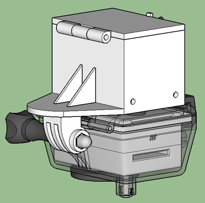
This package was designed in SketchUp. I found a GoPro adapter in the 3D warehouse that attaches to the camera housing itself, and then proceeded to redesign the entire box.
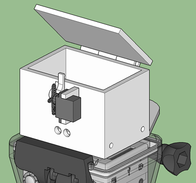
You can see the hinged lid on the top and holes on the side for securing parachute lines. Here’s the other side…
On this side, you can see the parachute deployment latch and a couple of holes for status LED’s to poke through.
Here’s an exploded view of the latch…
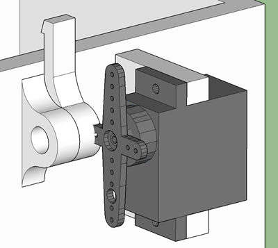
The latch itself is on a small hinged joint. A servo motor mount allows me to mount the motor that is going to pull the latch when it’s time for the parachute to deploy. I’m counting on the lid being under pressure (likely by use of a spring) in order to keep the lid closed securely and to eject the parachute well once the latch is tripped.
This entire package would be 3D printed in 3 parts - the box, the small latch, and the lid.
Inside the package would reside a smart device for reading sensors and figuring out how to behave (when to deploy the chute mainly). The plan is for that smart device to be an Intel Edison, because of its small form factor and because I have one on hand, but a variety of devices could be used.
According to the original plan, the device would require little more than an accelerometer and a battery for power.
Before I printed the package, I decided to get the electronic circuit prototyped and prooved out. And upon doing, I ran into a snag - a snag that has not quite killed, but certainly postponed the project. I must confess, the snag is entirely due to the amount of time between me and my high school physics courses.
The first thing to do in setting up the circuit was to wire up an accelerometer. Here’s the ADXL335 that I ended up using…
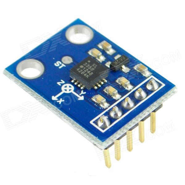
In case you’re interested in this stuff and don’t already know, there are basically two kinds of accerometers you can use for a project - analog and digital. The ADXL335 is analog. Analog accelerometers are easier to use and sometimes offer more resolution. With an analog accelerometer, after you’ve accomplished the simple task of providing it 3.3V power and ground, you wire three pints (for each of the three axes in our 3D world) to your smart device and each has a voltage value that represents the amount of acceleration (g-force) acting on that axis at any given moment in time. So reading an analog accelerometer is a simple matter of calling a function like .analogRead() or its equivalent on each of the three inputs.
When you have an accelerometer installed into a device securely and permanently, then it’s orientation may have some meaning. If you put it in a car, then you may care, for instance, about the fact that X is the forward/backward axis, Y is the side to side axis, and Z is up and down. In this project, however, who knows what the orientation of the device is going to be in the air. It will likely be spinning all around. Especially considering the fact that the plan involves launching this from a vertical slingshot.
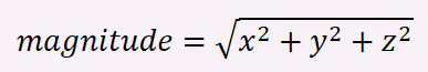
So the values of acceleration on the individual axes matter not. What matters is the overall acceleration on the unit. It didn’t take much web research to remind myself of the formula…
So, let me go ahead and list some simple code for determining this. This is JavaScript. If you’re interested in writing JavaScript on a device, then head on over to my Setting up an Intel Edison post and see how I got here.
var cylon = require('cylon');

cylon.robot({
    connection: { name: 'eddie', adaptor: 'intel-iot' },
    devices: [
        { name: 'x', driver: 'analogSensor', pin: 0 },
        { name: 'y', driver: 'analogSensor', pin: 1 },
        { name: 'z', driver: 'analogSensor', pin: 2 },
    ]
}).on('ready', function (eddie) {
    every((0.05).second(), function () {
        var m = mag(eddie.x.analogRead(), eddie.y.analogRead(), eddie.z.analogRead());
    });
}).start();

function mag(x,y,z) {
    return Math.sqrt(Math.pow(x,2) + Math.pow(y,2) + Math.pow(z,2));
}
Cylon is a JavaScript library that makes working with devices much easier. It happens to have a bridge for the Edison, so it’s all very easy to work with.
In the above code, I’m calling my Edison eddie and I’m polling the analog pins every 20th of a second and applying the aformentioned formula to determine the magnitude.
Then, I took my Edison, accelerometer, and a USB battery pack for power and rubber-banded it all together and threw it in the air and then caught it. Do you want to see the results? I certainly did. I have to say, I was surprised. Will you be?
Here’s the overall acceleration (the magnitude of all axes)…
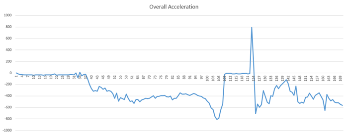
There was a value on the pins when I let the unit rest, and I subtracted that from all subsequent values.
I spend considerable time studying this chart with my wife (who is much smarter than me) and I have to admit there are still some parts that are a bit baffling. Here’s what (I think) I do know now…
- The ramp up before the flat line (from about 105 to 109) is my throw. That’s me adding acceleration to the unit.
- The flat line from 109 to about 122 is the span after leaving my hand and before catching it.
- The spike to a value of 800 at 123 or so is the moment the unit landed back in my hand and there’s a small rebound (bounce) at about 125.
Here’s what I’m certain I still don’t know about that chart…
- Why did the acceleration drop around 37 when (I believe) I picked the unit up from the table?
- Why did the acceleration drop between 97 and 106 just before I tossed the started my throw?
- Why is the steady value from 1 to 37 the same value as from 109 to 122 when the unit was in the air and being affected by gravity?
I may be reading the chart all wrong, and would certainly welcome your comments below.
In attempting to understand, I tweeked my code to create a delta between the last magnitude reading and the current one - a delta. The chart for the acceleration delta is perhaps a bit easier to understand…
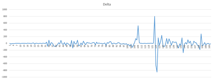
But the biggest discovery I got out of reading these charts was that…
I’m not going to be able to detect the apogee using an accelerometer.
My error was in thinking that the acceleration force on the unit would diminish as it ascended, zero out at its apogee, and start increasing again as it descended. Perhaps I was making a noobie mistake and thinking of the unit’s velocity. The fact (as I understand it now) is that straight line from 109 to 122 means there’s nothing at all that changes at the peak of the unit’s travel, and thus no way for me to launch my parachute with this data alone.
I researched how model rockets determine the same thing, and sure enough I discovered that they tend to use altimeters or human spotters with calculators (that’s a different kind of geeky).
I did have one idea as to how to make this work. I could do a little bit of math and add up the amount of energy that was put into throwing the unit. Because the resistence to that energy (gravity) is constant, I should be able to do a decent job of calculating how long this thing is going to be in the air, cut that in half and launch the parachute based on timing. I’m not exactly excited about doing the testing that that method requires, and that’s why this project is sliding.
Thanks for reading!
Addendum (2014-12-04)
Actually, the project is back on :) I’ll explain.
I love the process I had to go through to discover that an accelerometer would not work. I don’t mind not knowing things. I mind not learning things!
I attended a meetup of the KingMakers in Redmond the other day and had a good conversation with someone with some hobby rocket experience. He said that it’s very common to use barometric altimeters to measure altitude and that the resolution is very good - something like 1 foot! Wow. I would not have guessed. I quickly considered an altimeter, but dismissed it almost as quick thinking that the resolution would be too poor. After learning this, though, it didn’t take me long to find the MPL3115A2 from Adafruit.
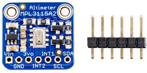
This bad boy is capable of .3m accuracy and even comes with a thermometer for temperature readings.
So with new information in my quiver, I’m back in the game. Look for more here on the GoChute project as progress unfolds.