Posts tagged with "maker"
My Top 5 Favorite Things at Maker Faire 2017
I attended the San Francisco Bay area recently to help welcome makers from around the globe to Maker Faire 2017.
This stalwort of all things maker is an inevitable blast. If you’ve ever been victim of maker’s block, this event will unstick you, and if you’ve ever been tempted to think that you were the most creative person on earth, this event will offer appropriate humility.
Here are the top 5 things I came across that I can’t wait to research, order, make, and talk about…
Microsoft Make Code
I know it seems like cheating to pick the Microsoft booth for this list since I work there, but hey, it’s my blog. And I think I would have picked it anyway, because the impact of the booth was awesome. The folks at Maker Faire seemed to agree too and showed it with two ribbons.
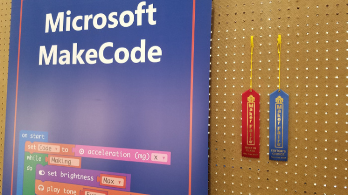
One of the showcased products at the booth was Microsoft Make Code.
Make Code is a new in-browser IDE from Microsoft that makes IoT development with a select few partner hardware boards about as simple as you can imagine. If you own a supported board (which we were giving away all weekend), check out these getting started steps…
- browse to makecode.com
- plug the device in to your USB port
That’s it!
We had everyone from 5 to 95 walking through a tutorial to write their first IoT app, and it was brilliant to see so many lights turn on - on the boards and in the minds of the new IoT hackers that were being made.
While I’m on the subject of awesome Microsoft displays, you can’t beat the Intelligent Kiosk app for Windows 10 that does a phenomenal job of showing of Microsoft Cognitive Services. This app take a picture every few seconds and runs it through Microsoft’s Cognitive Services API. It does things like associate your face with a dog breed, guess your age and gender, or try to determine your emotion. The results are comical.
You can download the app yourself too. There was hardly a single moment the entire 3-day weekend that there wasn’t a full crowd around each of two Intelligent Kiosk displays making silly faces and laughing out loud.
Maslow
Maslow (maslowcnc.com) is essentially an inexpensive and entirely open project for building a drawbot with a router. You’ve seen the drawbots before I’m guessing where two motors suspend a pen-wielding carriage on a steeply angled drawing surface. Drawings from the computer are translated into data that drives the motors and extends or retracts the pen to end up drawing a picture.
The Maslow is like that except that instead of a pen, it’s a router spinning at tens of thousands of RPM with a razor-sharp bit at the end. Yeah! Additionally, the plunge of the router is controlled, so you can program the depth of cut.
Check this out…
The net result is the ability to extract whatever 2D shapes you want from a large piece of plywood.
The interesting things about Maslow from my POV are…
- It’s cheap. You can get kits for under $500 to put the entire thing together
- It’s compact. Since it’s upright, you can fit it in a tight space.
- It’s open. You can extend or adapt the project to your needs.
Goliath CNC
Similar to the Maslow CNC router I already mentioned, the Goliath CNC project cuts things out for you, except instead of suspending a carriage it has you leave your workpiece flat and drives around it on a robot.
It’s like this…
Sometime ago I looked into the Shaper Origin and got excited about the ability to cut things out of stock of whatever size. Traditional CNC routers constrain you to a fixed size for your work piece. The impressive thing about both the Maslow and the Goliath as compared to the Origin is that not only do you get the infinite working area, but you don’t have to directly attend the cut. I wouldn’t leave the room, mind you, but the operator’s role is reduced from router-weilder to router-sitter, and that’s a bit of a relief.
I don’t know which - if any - of these machines will rise to earn the title of most useful in the long run, but they are all super good ideas and I’m excited to see evolve.
Monoprice 3D Printers
I’m big on 3D design, but I’ve yet to purchase my own 3D printer. This is partly due to the fact that I have access to some in nearby maker spaces.
If I were to purchase a printer today, though, I think I’d get one from Monoprice. Their MP Select Mini 3D Printer V2 is only $219, and their new Mini Delta 3D is available (for only 5 more days!) on Indiegogo for only $169!
You can count on problems with a printer at these price points, but then, you can pretty much count on problems with 3D printers at most price points. It’s hard to make a system reliable when there are so many variables.
The Monoprice’s printers are quite popular would seem to indicate ready availability of replacement parts to either buy or print.
Monoprice represented at the faire this year and showed off both their classic Mini as well as the new delta, and it’s great to see both in action.
PLY90
Sometimes it’s the simple things that have huge impact - like PLY90.

PLY90 is an aluminum bracket that holds plywood together at a 90 degree angle. Simple. But the projects you can make from something like this are endless. Here are a few I liked…


See more designs that take advantage of the PLY90 bracket at plyproducts.com/collections/projects.
Hydroponics A-Frame System
Bruce Gee of Waterworks was fascinating to listen to as evidenced by the constant crowd of folks standing around asking questions and busily writing down what he shared about his hydroponics experience. Bruce has a way of making hydroponics sound easy.

Bruce used simple and inexpensive lumber and PVC pipe to create an A-shaped structure for running water over the roots of plants, and that was pretty much the end of the story. Most hydroponics systems I’ve seen incorporate lighting and control systems that certainly add to crop growth, but also to overall complexity and threaten to to intimidate your average home farmer.
If you have never been to a Maker Faire, I beg you go to makerfaire.com and find one near you. We are all creators. You are too.
So what’s your next creation?!
The Most Basic Way to Access GPIO on a Raspberry Pi
I’ve been hacking on the Raspberry Pi of late and wanted to share out some of the more interesting learnings.
I think people that love technology love understanding how things work. When I was a kid I took apart the family phone because I was compelled to see what was inside that made it tick. My brother didn’t care. If it made phone calls, he was fine with it. I had to understand.
Likewise, I knew that I could use a Node library and change the GPIO pin levels on my Raspberry Pi, but I wanted to understand how that worked.
In case you’re not familiar, GPIO stands for General Purpose Input/Output and is the feature of modern IoT boards that allows us to controls things like lights and read data from sensors. It’s a bank of pins that you can raise high (usually to something like 3.3V) or low (0V) to cause some electronic behavior to occur.
On an Intel Edison (another awesome IoT board), the platform developers decided to provide a C library with mappings to Node and Python. On the default Edison image, they provided a global node module that a developer could include in his project to access pins. The module, by the way, is called libmraa.
On a Raspberry Pi, it works differently. Instead of a code library, a Pi running Raspbian uses the Linux file system.
When you’re sitting at the terminal of your pi (either hooked up to a monitor and keyboard or ssh’ed in), try…
cd /sys/class/gpio |
You’ll be taken to the base of the file system that they chose to give us for accessing GPIO.
The first thing to note is that this area is restricted to the root user. Bummer? Not quite. There’s a way around it.
The system has a function called exporting and unexporting. Yes, I know that unexport is not a real word, but alas I’m not the one that made this stuff up, and besides, who said Linux commands had to make sense?
To access a pin, you have to first export that pin. To later disallow access to that pin, you unexport it.
I had a hard time finding good documentation on this, but then I stumbled upon this znix.com page that describes it quite well. By the way, this page references “the kernel documentation,” but when I hit that link here’s what I get…

Oh well.
Now keep in mind that to follow these instructions you have to be root. You cannot simply sudo these commands. There is an alternative called gpio-admin that I’ll talk about in a second. If you want to just become root to do it this way, you do…
su root |
If you get an error when you do that, you may need to first set a password for root using sudo passwd.
To export then, you do this…
echo <pin number> > /sys/class/gpio/export |
And the pin number is the pin name - not the header number. So pin GPIO4 is on pin 7 on an RP2, and to export this you use the number 4.
When you do that, a virtual directory is created inside of /sys/class/gpio called gpio4, and that directory contains virtual files such as direction, value, edge, and active_low. These files don’t act like normal files, by the way. When you change the text inside one of these files, it actually does something - like perhaps the voltage level on a GPIO pin changes. Likewise, if a hardware sensor causes the voltage level on a pin to change, the content of one of these virtual files is going to change. So this becomes the means by which we communicate in both directions with our GPIO pins.
The easiest way, then, to read the value of the /sys/class/gpio/gpio4/value file is…
cat /sys/class/gpio/gpio4/value |
Easy.
To write to the same file, you have to first make sure that it’s an out pin. That is, you have to make sure the pin is configured as an output pin. To do that, you change the virtual direction file. Like this…
echo out > /sys/class/gpio/gpio17/direction |
That’s a fancy (and quick) way to edit the contents of the file to have a new value of “out”. You could just use vi or nano to edit the file, but using echo and the direction operator (>) is quicker.
Once you have configured your pin as an output, you can change the value using…
echo 0 > /sys/class/gpio/gpio4/value //set the pin low (0V) |
Now that I’ve described the setting of the direction and the value, you should know that there’s a shortcut for doing both of those in one motion…
echo high > /sys/class/gpio/gpio4/direction |
There’s more you can do including edge control and logic inversion, but I’m going to keep this post simple and let you read about that on the znix.com page.
Now, although it’s fun and satisfying to understand how this is implemented, and it might be fun to manipulate the pins using this method, you’ll most likely want to use a language library to control your pins in your app. Just know that the Python and Node libraries that change value are actually just wrappers around these file system calls.
For instance, let’s take a look at the pi-gpio.js file in the pi-gpio module…
write: function(pinNumber, value, callback) { |
When you call the write() method in this library, it’s just calling the file system.
So there you have it. I hope you feel a little smarter.
Easy and Offline Connection to your Raspberry Pi
Getting a Raspberry Pi online is really easy if you have an HDMI monitor, keyboard, and mouse.
Subsequently getting an SSH connection to your pi is easy if you have a home router with internet access that you’re both (your PC and your pi) connected to.
But let’s say you’re on an airplane and you pull your Raspberry Pi out of its box and you want to get set up. We call that provisioning. How would you do that?
I’ll propose my method.
First, you need to plug your pi into your PC using an ethernet cable. If you’re a technologist of old like I am, you may be rummaging through your stash for a crossover cable at this point. It turns out that’s not necessary though. I was pretty interested to discover that modern networking hardware has auto-detection that is able to determine that you have a network adapter plugged directly into another network adapter and crosses it over for you. This means I only have to carry one ethernet cable in my go bag. Nice.
If you put a new OS image on your pi and boot it up, it already detects and supports the ethernet NIC, so it should get connected and get an IP automatically.
Here comes the seemingly difficult part. How do you determine what the IP address of your pi is if you don’t have a screen?
The great thing is that the pi will tell you if you know how to listen.
The means by which you listen is called mDNS. mDNS (Multicast DNS) resolves host names to IP addresses within small networks that do not have a local name server. You may also hear mDNS called zero configuration and Apple implemented it and felt compelled (as they tend to) to rename it - they call it Bonjour.
This service is included by default on the Raspberry Pi’s base build of Raspbian, and what it means is that out of the box, the pi is broadcasting its IP address.
To access it, however, you also need mDNS installed on your system. The easiest way I am aware of to do this is to download and install Apple’s Bonjour Print Services for Windows. I’m not certain, but I believe if you have a Mac this service is already there.
Once you have mDNS capability, you simply…
ping raspberrypi.local -4 |
The name raspberrypi is there because that’s the default hostname of a Raspberry Pi. I like to change the hostname of my devices so I can distinguish one from another, but out of the box, your pi will be called raspberrypi. The .local is there because that’s the way mDNS works. And finally, the -4 is an argument that specifically requests the IPv4 address.
If everything works as expected you’ll see something like…
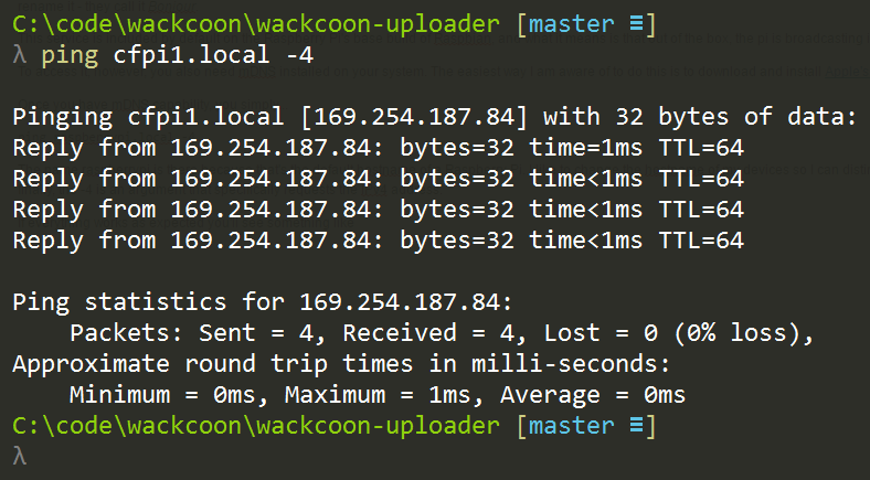
Again, my pi has been renamed to cfpi1, but yours should be called raspberrypi if it’s new.
My system uses 192.168.1.X addresses for my wireless adapter and 169.254.X.X for my ethernet adapter.
So that’s the information I needed. I can now SSH to the device using…
ssh pi@169.254.187.84 |
I could just use ssh pi@raspberrypi.local to remote to it, but I’ve found that continuing to force this local name resolution comes with a little time cost, so it’s sometimes significantly faster to hit the IP address directly. I only use the mDNS to discover the IP and then I use the IP after that.
Provisioning a Raspberry Pi usually includes a number of system configuration steps too. You need to connect it to wireless, set the locale and keyboard language, and maybe turn on services like the camera. If you’re used to doing this through the Raspbian Configuration in XWindows, fear not. You can also do this from the command line using…
sudo raspi-configuration |
Most everything you need is in there.
You may also be wanting to tell your pi about your wifi router so it’s able to connect to via wireless the next time you boot up. For that, check out my post at codefoster.com/pi-wifi. Actually, if you’re playing a lot with the Raspberry Pi, you might want to visit codefoster.com/pi and see all of the posts I’ve written on the device.
Happy hacking!
Accidental Old Version of Node on the Raspberry Pi
I beat my head against a wall for a long time wondering why I wasn’t able to do basic GPIO on a Raspberry Pi using Node. Even after a fresh image and install, I was getting cryptic node error messages when I ran my basic blinky app.
Lucky for me (and perhaps you) I got to the bottom of it and am going to document it here for posterity. Let’s go.
The head beating happened at a hackathon I recently attended with some colleagues.
The task was simple - turn on an LED. It’s so simple that it’s become the “hello world” app of the IoT world. There’s zero reason in the world why this task should take more than 10 minutes. And yet I was stumped.
After a fresh image of Raspbian, an install of NVM, and then a subsequent installation of Node.js 6.2.2, I wrote a blink app using a variety of modules. I used pi-gpio, rpi-gpio, onoff, and finally johnny-five and the raspi-io driver.
None of these strategies were successful. Ugh. Node worked fine, but any of the libraries that accessed the GPIO were failing.
I was getting an obscure error about an undefined symbol: node_module_register. No amount of searching was bringing me any help until I found this GitHub issue where nodesocket (thanks, nodesocket!) mentioned that he had the same issue and it was caused by an NVM install of Node and an accidental, residual version of node still living in /usr/local/bin. In fact, that was exactly what was happening for me. It was a subtle issue. Running node -v returned my v6.2.2. Running which node returned my NVM version. But somewhere in the build process of the GPIO modules, the old version (v0.10) of node from the /usr/local/bin folder was being used.
There are two resolutions to this problem. You can kill the old version of node by deleting the linked file using sudo rm /usr/local/bin/node and then create a new one pointing to your NVM node. I decided, however, to deactive NVM…
nvm deactivate |
…and then follow these instructions (from here) to install a single version node…
wget http://nodejs.org/dist/v6.2.2/node-v6.2.2-linux-armv7l.tar.xz`` # Copied link |
I like using NVM on my dev machine, but it’s logical and simpler to use a single, static version of Node on the pi itself.
EDIT (2016-12-14): Since writing this, I discovered the awesomeness of nvs. Check it out for yourself.
And that did it. I had blinky working in under 3 minutes and considering I get quite obsessive about unresolved issues like this, I had a massive weight lifted.
BTW, through this process I also learned about how the GPIO works at the lowest level on the pi, and I blogged about that at codefoster.com/pi-basicgpio.
Wifi on the Command Line on a Raspberry Pi
I hate hooking a monitor up to my Raspberry Pi. It feels wrong. It feels like I should be able to do everything from the command line, and the fact is I can.
If you’re pulling your Raspberry Pi out of the box and are interested in bootstrapping without a monitor, check out my other post on Easy and Offline Connection to your Raspberry Pi.
Afterward, you may want to set up your wifi access - that is, you want to tell your pi about the wireless access points at your home, your coffee shop, or whatever.
Doing that from the command line is pretty easy, so this will be short.
You’re going to be using a utility on Raspbian called wpa_cli. This handles wireless configuration and writes its configuration into /etc/wpa_supplicant/wpa_supplicant.conf. You could even just edit that file directly, but now we’re talking crazy talk. Actually, I do that sometimes, but whatever.
First, run…
wpa_cli status |
…to see what the current status is. If you get Failed to connect to non-global ctrl_ifname: (null) error: No such file or directory, that’s just a ridiculously cryptic error message that means you don’t have a wifi dongle. Why they couldn’t just say “you don’t have a wifi dongle” I don’t know, but whatever.
If you do have a wifi dongle, you’ll instead see something like…

Yay! You have a wireless adapter, which means you likely have a wifi dongle plugged into a USB port. It says here that the current state is INACTIVE. That’s because you’re not connected to any access points.
To do so, you need to run scan, but at this point, you may want to enter the wpa_cli interactive mode. That means that you don’t have to keep prefixing your commands with wpa_cli, but can instead just type the commands. To enter interactive mode, just do…
wpa_cli |
To get out at any time just type quit <enter>.
Now do a scan using…
scan |
It’s funny, because it appears that nothing happened, but it did. Use…
scan_results |
…to see what it found.
This scanning step is not necessary, by the way, there’s a good chance you already know the name (SSID) of your access point, and in that case you don’t need to do this.
Next you create a new network using…
add_network |
You’ll get an integer in return. If it’s your first network, you’ll get a 0. That’s the ID of the new network you just created, and you’ll use it on these subsequent commands.
To configure your network do this…
set_network 0 ssid "mynetwork" |
Something I read online said that as soon as you enter this, it would start connecting, but I had to also do this to get it to connect…
select_network 0 |
Now there’s one more thing. If you’re like me, you don’t just connect to a single AP. I connect from home, my mifi, my local coffee shop, from work, etc. I want my pi to be able to connect from any and all of those networks.
Adding more networks is as easy as following the instructions above multiple times, but you want to set one more network property - the priority. The priority property takes an integer value and higher numbers are higher priority. That means that if I have network1 (priority 1) and network2 (priority 2), and when my pi boots it sees both of those networks, it’s going to choose to connect to network2 first because it has the higher priority.
Okay, that does it.
If you want to see everything I’ve written about the Raspberry Pi, check out codefoster.com/pi
Index of my Raspberry Pi Posts
I’ve been doing a lot of hacking on the Raspberry Pi, and I’ve written a few articles on the topic. I’ve assembled all of my posts here for easy access.
- Accidental Old Version of Node on the Raspberry Pi - I beat my head against a wall for a long time wondering why I wasn’t able to do basic GPIO on a Raspberry Pi using Node. Even after a fresh image and install, I was getting cryptic node error messages when I ran my basic blinky app.Lucky for me (and perhaps you) I got to the bottom of it and am going to document it here for posterity.
- The Most Basic Way to Access GPIO on a Raspberry Pi - I’m always looking for the lowest level understanding, because I hate not knowing how things work. On a Raspberry Pi, I’m able to write a Node app that changes GPIO, but how does that work? Turns out it’s pretty interesting. I’ll show you.
- Easy and Offline Connection to your Raspberry Pi - Getting a Raspberry Pi online is really easy if you have an HDMI monitor, keyboard, and mouse, but what about if you want to get connected to your Pi while you’re, say, flying on a plane?
- Wifi on the Command Line on a Raspberry Pi - How to configure wireless connections on your Raspberry Pi from the command line.
Building Things Using Fusion 360 and JavaScript
I like making things.
I used to mostly just make things that show up on the computer screen - software things. Lately, however, I’ve been re-inspired to make real things. Things out of wood and things out of plastic and metal and fabric and string.
The way I see it, we design things either manually or generatively.
By manual I mean that I conceive an idea then design and build it step by step. I - the human - am involved every step of the process. Imperative code is manual. Here’s some pseudocode to describe what I’m talking about…
// step 1 |
See what I mean?
I’m not arguing that this sort of code and likewise this sort of technique for building is not essential. It is. I am, however, going to propose that it’s often not altogether exciting or inspiring. The reason, IMO, is that the entire process is no greater than the individual or organization that implements it. An individual only has so many hours in the day and is even limited in ideas. An organization can grow rather large and put far more time and effort into a problem and obviously generate more extensive results. But the results are always linearly related to the effort input - not so exciting.
By generative I mean that instead of creating a thing, I create rules to make a thing. The rules may be non-deterministic and the results completely unexpected - even from one run to another. The results often end up looking very much like what we find in nature - the fractal patterns in leaves, the propagation of waves on the water, or the absolute beauty of ice crystals up close.
What’s exciting is when an individual or organization puts their time and effort into defining rules instead of defining steps. That is, after all, the way our own brains work, and in fact, that’s the way the rest of nature works too. It’s amazing and awesome and I would venture to say it’s even miraculous.
I think a lot of my ideas on the matter parallel and perhaps stem from Stephen Wolfram’s book A New Kind of Science.

Most of the book is about cellular automata. The simple way to understand these guys is to think back to Conway’s Game of Life. The game is basically a grid of cells that each have a finite number of states - often times two states: black and white. Initially, the cells in the grid are seeded with a value and then iterations are put into place that may change the state of the cells according to some rules.
The result is way more interesting than the explanation. The cell grid appears to come to life. The fascinating part is that the behavior of the system is usually not what the author intended - it’s something emergent. The creator is responsible for a) creating an initial state and b) creating some rules. The system handles the rest. It usually takes a lot of trial and error if the intention is to create something that serves some certain purpose.
Check out Wikipedia’s page on cellular automata, and specifically look at Gosper’s Glider Gun.
I don’t know about you, but I find that completely awesome.
Okay, so when are you going to get to the point of the blog post, codefoster?
Calm down. It’s called build up. :)
First, let me say that generating graphics in either 2D or 3D is nothing conceptually new. What I like about discovering and learning an API for CAD software, though, is that I can not only generate something that targets the screen, I can generate something that targets the 3D printer or the laser cutter. That’s all sorts of awesome!
The example I’m going to show you now is a simple one that I hope will just get your gears turning. You could, by the way, take that literally and generate some gears and get them turning.
If you don’t have Fusion 360, go to fusion360.autodesk.com and download it. If you’re a hobbyist, maker, student, startup type you can get it for free.
If you’re new to the program, let me suggest the learning material on their website. It’s great.
After you install Fusion 360, the first thing you need to do is launch the program. This API is attended. It requires that you open the program and launch the scripts. I have suggested to the team at Autodesk to research and consider implementing unattended scenarios as well.
Now launch the Scripts and Add-ins… option from the File menu…
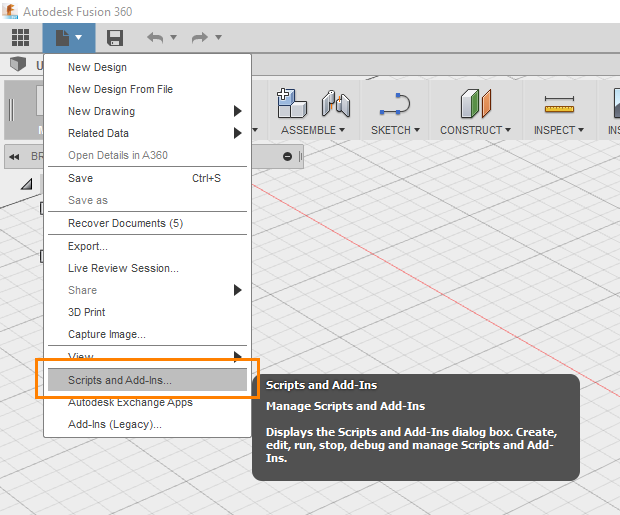
Don’t be confused by the Add-Ins (Legacy) option in the same File menu. That’s for an old system that you don’t want to use anymore.
That should launch the Scripts and Add-Ins dialog…
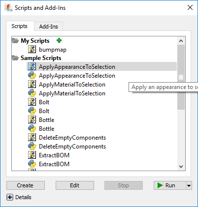
There are two tabs - Scripts and Add-Ins. They’re the same thing except that Add-Ins can be run automatically when Fusion 360 starts and can provide commands that the user can see in their UI and invoke by hitting buttons. Add-Ins ask you to implement an interface of methods that get called at certain times. If you simply click the Create button on the Add-Ins page, it will make you a sample with most of that worked out for you already.
Let’s focus on the Scripts tab for now.
You’ll see a number of sample scripts in there. Some of them will have the JavaScript icon…  …and others will have the Python icon…
The Fusion 360 API supports 3 languages: C++, Python, and JavaScript.
Above those, you’ll see the My Scripts area that contains any scripts you have written or imported.
It’s not entirely clear at first how this works. Let me explain. If you click Create at the bottom, you’ll get a new script written in a strange folder location. It’s good because it gives you the right files (a .js file, an .html file, and a .manifest), but it’s bad because it’s in such an awkward location. The best thing to do in my opinion is to hit create and get the sample code files and then move the files and their containing folder to wherever you keep your code. Then you can hit the little green plus and add code from wherever you want.
One more nuance of this dialog is that if you click the Edit button, Fusion 360 will launch an IDE of its choice. I think this is weird and should be configurable. If I edit a JavaScript file it launches Brackets. I don’t use Brackets. I use Visual Studio Code. It doesn’t end up being that much trouble, but it’s weird.
To edit my code, I just go to my command line to whatever directory I decided to put it in and I type…
code . |
That launches Code with this directory as the root. Here’s what I see…
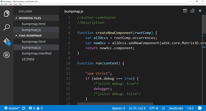
There you can see the .html, .js, and .manifest files.
I’m not going to take the screen real estate to walk you entirely through the code. You can see it all on GitHub. But I’ll attempt to show you what it’s doing at a high level.
Here’s the code…
<style type="text/css">.gist {width:700px ;} |
Let’s break that down some.
The createNewComponent function is just something I made. That’s not a special function the API is expecting or anything. The run function is, however, a special function. That’s the entry point.
Essentially, I’m creating a 20x20 grid, prompting the user to select a body, and then doing a 2D loop to copy the selected body. The position is all done using a transformation that shifts each body into place and then offsets it a certain amount in the Z direction. In this case, I’m just using a random number, but I could very well be feeding data in to this and doing something with more meaning.
Watch this short video as I create a cube and then invoke this script on it…
So, here is where you just have to sit back and stare at the ceiling and think about what’s possible - about all the things you could generate with code.
My example was a basic, linear iterator. Perhaps, however, you want to create something more organic - more generative?
Check out this example by Autodesk’s own Mike Aubry (@Michael_Aubry) where he uses Python code to persuade Fusion 360 to build a spiral using the API.

That has a bit more polish than my gray cubes!
If you build something, make sure you toss a picture my way on Twitter or something. I’d love to see it.
Help Me Design a Candy Dispenser
I’m going to keep much of my latest project under wraps for now, but I need your help designing one piece of it.
I’m looking to create a device that is small and light and will dispense one piece of candy at a time programmatically.
Here are the requirements…
- Light - no more than 1oz
- One at a time - it needs to dispense a piece of candy one at a time. If I have to constrain it to hold only round candy of a set size, then so be it, but ideally it would hold candy of varying size and shape. Ideally it will hold Runts bananas.
- It has to operate on a 3.7V power supply
- It has to be an electro-mechanical assembly that I can control with an IoT device (an easy req to fulfill I think)
- It should hold some reasonable number of candy pieces - say at least 10.
So far I’ve thought of the following…
- An Archimedes screw that “pumps” candy up from the bottom of a hopper (like this)
- A wheel that sits horizontal and on each incremental rotation lets one candy piece at a time fall into a hole in the top and lets another fall out a hole at the bottom
- A screw that sits on a horizontal axis that is loaded with candy pieces (one per screw rotation… not in a hopper) and pushes one piece out at a time when rotated 360 degrees. A bit like snack vending machines.
If you can come up with any other brilliant ideas, I’d be glad to hear them.
Thanks in advance.
Command Monkey
Alright, this is going to be fun. The process is going to be fun, and the end game is going to be even more so.
Let me paint a picture of the final product. I have a monkey toy on the table before me. I then hold my Microsoft Band up to my mouth and talk into it like Maxwell Smart. I say two simple words - “Monkey, dance!”
And in no time flat, the monkey toy obeys my command and is set into motion.
The whole thing reminds you of Tweet Monkey and it should. This is Tweet Monkey’s older and slightly more involved brother.
Where Tweet Monkey was a device to cloud scenario, Command Monkey is a Cortana to phone app to cloud to device scenario. Where Tweet Monkey relied on the Twitter Streaming API (which is very cool), Command Monkey involves our very own streaming API using web sockets.
I know it sounds like it’s going to be a lot of code, but it’s really not. You’ll see. Let me just say too that if for some reason you don’t have any interest in going through this step by step, then don’t. Just go grab the code on GitHub, because that’s how we roll.
I’m going to be using the free community version of Visual Studio and the Node.js Tools for Visual Studio. You could obviously use anything beyond an abacus to generate ASCII, so let’s not get opinionated here. Use what you love. It should go without saying that you’ll need Node.js installed to make this work. That can be found at nodejs.org.
I’m going to host my Node.js project in Azure and in fact, I’m going to get it there in a rather cool way. I’m going to use the cross platform CLI for Azure to create the site and then I’ll use git deployment to publish the app.
The architecture diagram is going to look something like this…
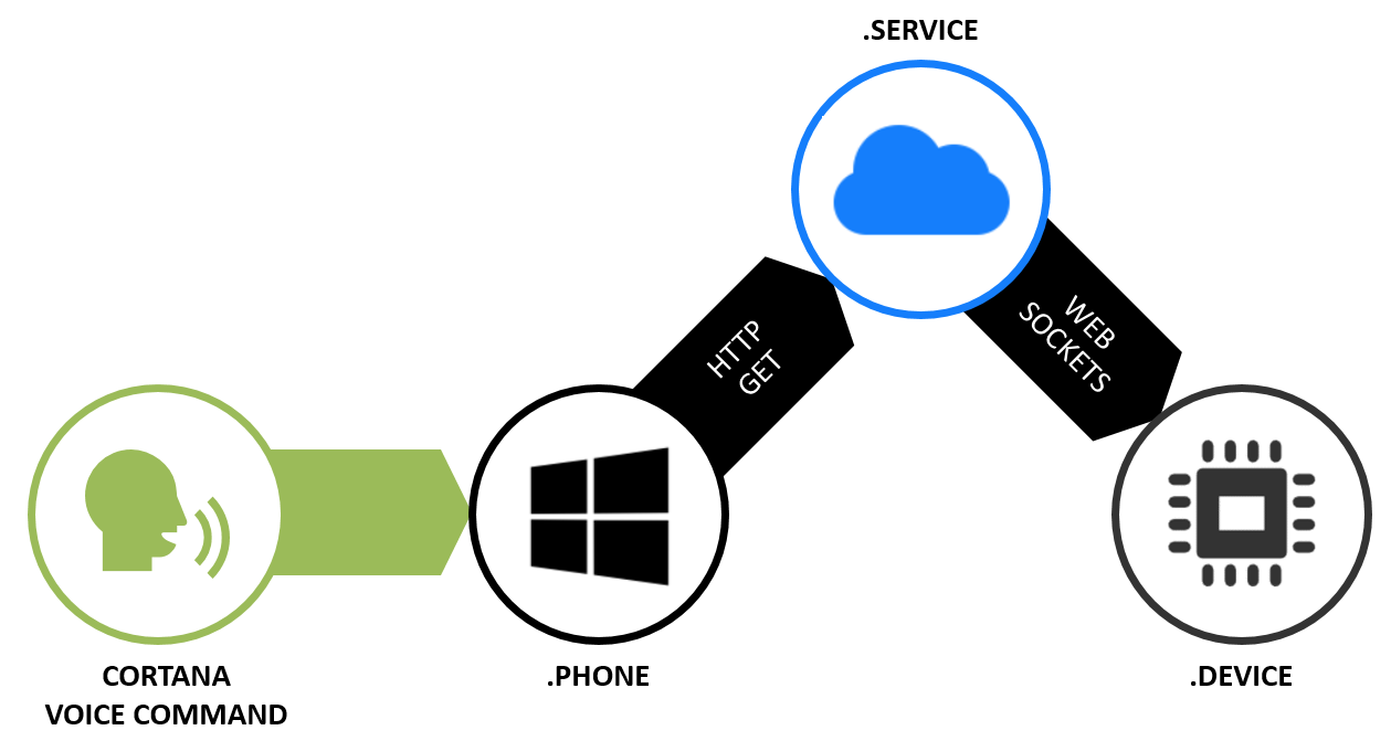
The part about speaking the command into a Microsoft Band just looks like special sauce, but you get that for free with a Band. The Band already knows how to talk to Cortana on your phone.
You will need to teach Cortana to talk to you app, so let’s do that first. Let’s build a Windows Phone app.
Building the Phone App
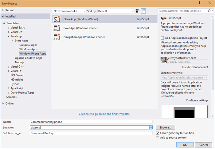
In Visual Studio, hit File | New | Project and create a blank Windows Phone App using JavaScript called CommandMonkey.phone. Call the solution just CommandMonkey. Like this…
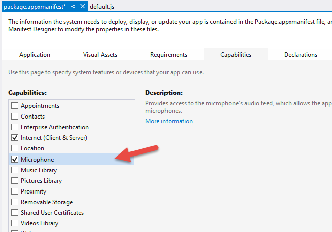
In order to customize Cortana, we need to define a voice command and that requires the Microphone capability. To add that, double click on your package.appxmanifest, go to the Capabilities tab, and check Microphone…
Now we need to create a Voice Command Definition (VCD) file. This file defines to Cortana how to handle the launching of our app when the user talks to her. Here’s what you should use…
|
The interesting bits are lines 6 and 9-14. The combination of the prefix with the command name means that we’ll be able to say “Monkey dance” and Cortana will understand that she should invoke the Command Monkey app and use “dance” for the command.
You’ll notice that I have a second command in the phrase list for the command - chatter. I don’t currently have a mechanical monkey capable of both dancing and chattering, but you can imagine a device capable of doing more than one action and so the capability is already stubbed out.
Next we need to register this VCD file in our phone app. When we do this and then install the app on a phone, Cortana will then have awareness of the voice capabilities of this app. She’ll even show it to the user when they ask Cortana “What can I say?” To do that, open the js/default.js file and add this to the beginning of the onactivated function…
var sf = Windows.Storage.StorageFile; |
And there’s one more step to completing the Cortana integration. We need to actually do something when our application is invoked using this voice command.
Still in the default.js, add this after the if statement that is looking for the activation.ActivationKind.launch
else if (args.detail.kind === activation.ActivationKind.voiceCommand) { |
Now let’s talk about what that does.
The if statement we hung that else if off of is checking to see just how the app was launched. If the user clicked the tile on the start screen, then the value will be activation.ActivationKind.launch. But if they activated it using Cortana then the value will be activation.ActivationKind.voiceCommand, so this is simply how we handle that case.
The way we handle it is to access the parsed semantic using the event argument and then to send whatever command the user spoke to the CommandMonkey.azurewebsites.net website.
How did that website get created you might ask? I’m glad you did, because we’ll look at that next. As for the phone project, that’s it. We’re done. It’s not fancy, and in fact if you run it, you’ll see the default “Content goes here” on a black screen, but remember, we’re keeping this simple.
Building the Node.js Web Service
Visual Studio is able to hold multiple projects in a single solution. So far we have a single solution (called CommandMonkey) with a Windows Phone project (called CommandMonkey.phone).
Now we’re adding the web service.
Find the solution node in Visual Studio’s Solution Explorer and right click on it and choose Add | New Project…
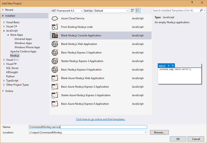
Now install the express and socket.io Node modules. You can either do it the graphical way or the command line way.
The graphical way is to right click on npm in the .service project and choose Install New npm Packages… Then search for and install express and socket.io. For each leave the Add to package.json checked so they’ll be a part of your project’s package.json.
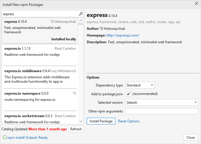
Now the command line way. Navigate to the root of this project at a command line or in PowerShell and enter npm install express socket.io --save
Now open up the app.js and paste this in…
var http = require('http'); |
This is not a lot of code for what it’s doing. This is…
- creating a web server
- setting up web sockets using socket.io
- setting up a handler for when clients call the ‘setTarget’ event
- defining a route to /api/command which calls the “target” client with the specified command
That’s what I love about JavaScript and Node.js. The code is short enough to really be able to see the essence of what’s going on.
Okay, the service is done, but it’s still local. We need to get this published.
We’re going to use Azure Websites feature called git deployment.
There’s something interesting about our project though. The git repository would exist at the solution level and include all of our code, but the folder that contains the Node.js project that we actually want published to Azure is in a subdirectory called CommandMonkey.service. So we need to create a “deployment file”. To do that just create a file at the root of the project called .deployment and use this as the contents…
[config] |
And in typical fashion, we’re going to have a few files that we have no interest in checking in to source control, so make yourself a .gitignore file (again at the root of the CommandMonkey solution) and use this as the content…
node_modules |
Now git commit the project using…
git init |
Now you need to create an Azure website. Note, you need to already have your account configured via the Azure xplat-cli in order to do this. I’ll consider that task outside the scope of this article and trust you can find out how to do that with a little internet searching.
azure site create CommandMonkey --git |
And of course, you can’t use CommandMonkey, because I’ve already used that one, but you can come up with your own name.
The --git parameter, by the way, tells the create command to also set up git deployment on the remote website and will also create a git remote in the local repository so that you’ll be able to execute the next line.
To publish the website to azure, just use…
git push azure master |
…and that will push all of your code to a repository in Azure and will then fire off a process to deploy the site for you out of the CommandMonkey.service directory which you specified earlier.
There’s one thing you need to do in the Azure portal to make this work. If anyone knows how to do this from the xplat-cli, be sure to drop me a comment below. I’d love to know. You need to turn on web sockets. Just go to your website in the portal, go to the configuration tab, and find the option to turn on web sockets. Easy.
Whew, done with that. Not so hard. Now it’s time to write the Node.js app that’s going to represent the device.
Building the Device Code
As is often the case, the device project is the simplest project in the solution. It does, after all, only have one job - listen for socket messages and then turn the relay pin high for a couple seconds. Let’s go.
In Visual Studio, right click on the solution and Add | New Project… and add another blank Node.js app. This time call it CommandMonkey.device…
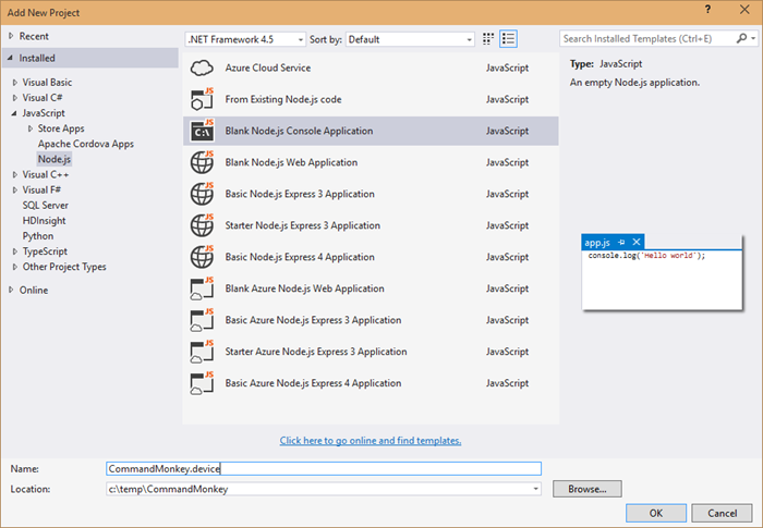
Using the technique above for installing npm packages, install the socket.io-client npm package.
var cylon = require('cylon'); |
You can see that this code is connecting to our web service in Azure - CommandMonkey.azurewebsites.net.
It also requires and initializes the Cylon library so it can talk to the hardware in an easy, expressive, and modern way.
The Cylon work method is like Cylon’s ready method, and so that’s where we’ll invoke the setTarget event. This socket event request for the server to save this socket as the “target” socket. That just means that when anyone triggers messages on the server, this is the device that’s going to pick them up. You may want to create this as an array and thus allow for multiple devices to be targets, but I’m keeping it simple here.
Finally, it handles the ‘command’ event that the server is going to pass it and simply raises the digital pin for 2 seconds.
To make this work, you need to deploy this project to your device. I use an Intel Edison, but this will work on any SoC (System on a Chip) that will run Linux. I am not going to repeat how to setup the Edison or deploy to it. You can find that in my series of Intel Edison posts indexed at codefoster.com/edison.
Once you get the code deployed to the device, you then run the CommandMonkey.phone project on your phone emulator or on your device. I run mine directly on my device so I can talk to my Microsoft Band.
And that should pretty much do it. If I haven’t made any gross errors in relaying this and you haven’t made any errors typing or pasting it in, then you’re scenario should work like mine. That is… you hold the action button on your Microsoft Band and say…
“Monkey, dance!”
…and a very short time later you get a message with the command on the screen.
I hope you’re mind is awhir like mine is with all the ideas for things you could do with this. We have real time device to device communication going on, and users really get excited when they utter a command and a half a second later something is happening in front of them.
Go. Make.
I recorded a CodeChat episode with my colleague Jason Short (@infinitecodex) about Command Monkey. Here you go…
